
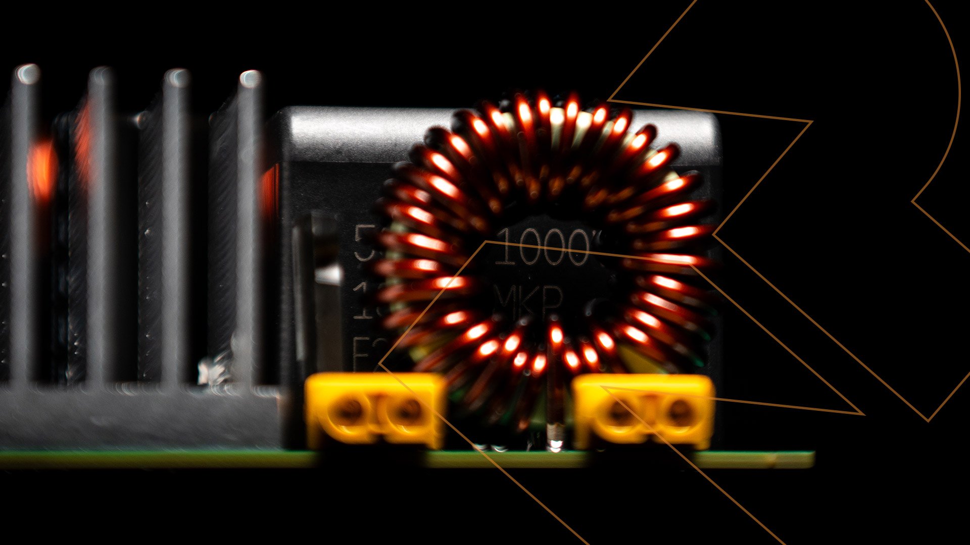
What is Active Magnetics?(Technical Foundation)
Engineering Principle
Active magnetics is a method to synthesize inductive behavior using a controlled power-electronic system, instead of relying solely on magnetic energy storage.
In a conventional inductor, the impedance is defined by:
v(t)=L⋅di(t)dtv(t)=L⋅dtdi(t)
This requires physical energy storage in a magnetic field proportional to L⋅i2L⋅i2, driving the need for large cores and copper windings.
In contrast, an active inductor separates the electrical function (impedance shaping) from physical energy storage by introducing a controlled auxiliary circuit. The system dynamically injects a compensating voltage and current such that the terminal behavior matches that of a much larger passive inductor over the frequency range of interest.
System Architecture
An active magnetics implementation typically consists of four tightly coupled subsystems:
1. Reduced Physical Inductor Core
A small inductance (often 20–30% of the equivalent passive value) handles the high-frequency ripple and provides a physical current path.
2. Power Electronic Conversion Stage
A bidirectional converter (typically H-bridge or full-bridge topology) generates the required compensating voltage across the terminals.
The converter injects a controlled current component that is phase-shifted relative to the ripple content, effectively canceling undesired harmonics in the main current path.
3. Energy Buffer (DC-side Capacitor)
A capacitor provides temporary energy storage to enable bidirectional power flow within the auxiliary circuit. It supports the emulation of inductive energy exchange without requiring large magnetic storage.
4. Control and Measurement System
The control system is the defining element. It continuously measures:
terminal voltage
inductor current
harmonic content
Based on this, it computes a reference current that enforces the desired impedance.
Typical control structure includes:
inner current loop (fast, hysteresis or PWM-based)
outer voltage loop (stabilization and loss compensation)
Impedance Synthesis Mechanism
The effective impedance seen from the terminals is determined by the interaction between the physical inductor and the controlled current source:
Zactive(s)=L1s1+Gr(s)Zactive(s)=1+Gr(s)L1s
Where:
L1L1 = physical inductance
Gr(s)Gr(s) = control transfer function
By shaping Gr(s)Gr(s), the system can extend the apparent inductance beyond the physical limitation of the core.
Minimal Energy Processing Principle
A key innovation in this architecture is that the auxiliary circuit processes only the ripple components:
it handles a fraction of the total current
it sees only low-frequency harmonic voltage components
This results in a minimum apparent power requirement, significantly improving efficiency and reducing semiconductor stress compared to earlier active inductor concepts.
Dynamic and Adaptive Behavior
Unlike passive inductors with fixed impedance, active magnetics enables real-time impedance control.
The equivalent inductance LeqLeq becomes a controlled variable:
increased under high harmonic distortion
reduced under light load
This is achieved through adaptive control strategies that monitor:
THD
DC-link ripple
system operating conditions
The system adjusts inductance dynamically to maintain performance targets across varying conditions.
Multi-Objective Control (Advanced Implementation)
Advanced implementations introduce multi-loop control strategies, where the system simultaneously optimizes:
grid-side current distortion (THD)
DC-link ripple
system stability under imbalance
A supervisory control layer selects the dominant objective depending on operating conditions, enabling robust performance even under:
grid voltage imbalance
load transients
harmonic disturbances
Integration into Power Electronic Systems
Active magnetics is not a standalone laboratory concept—it is designed to integrate directly into standard topologies:
DC-link filtering in motor drives
AC grid-side filtering
rectifier/inverter systems
From a system perspective, it behaves as a two-terminal plug-and-play component with identical electrical interfacing as a passive inductor.
Engineering Implications
Decoupling Function from Physics
The key paradigm shift is that inductance is no longer constrained by magnetic material limits. Instead, it becomes a software-defined parameter.
Performance Scalability
Higher power density
Reduced material dependence (copper, ferrite)
Improved system integration flexibility
System-Level Impact
Reduced footprint and weight
Improved power quality
Reduced stress on capacitors and downstream components
Summary
Active magnetics replaces conventional inductors by synthesizing their electrical behavior using a controlled power-electronic architecture.
It combines:
reduced physical inductance
power conversion
real-time control
to achieve:
equivalent impedance behavior
significantly lower energy storage
adaptive system performance
This transforms the inductor from a passive constraint into an active, controllable system element, enabling a new level of integration and optimization in modern power electronics.
Work with us
We are currently working with industry partners to bring active magnetics into commercial applications.